


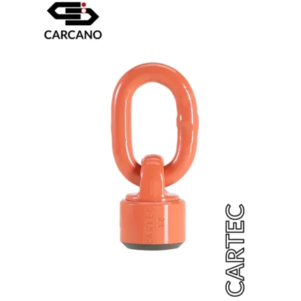
Rotating Restraining Device H.T. (PPE) – Grade 100 – Cartec
Rotating Restraining Device H.T. (PPE) – Grade 100 – Cartec
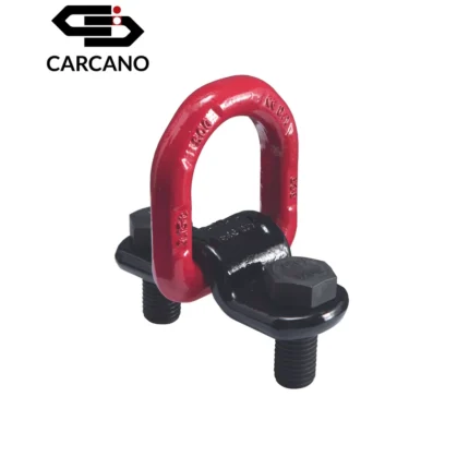
Device 900XHT is a safe arrest point to which anchoring one’s body harness (harness compliant to EN361) through a suitable connection system (compliant to EN362) to prevent falls and their effects during work operations at height.
- The threaded hole must be perpendicular to the supporting structure
- Tighten the device until it fits tightly against the surface
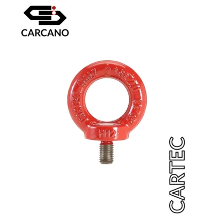
The eyebolt with the product code C900XHT is Grade 100, for the corresponding eyebolt
with screw
click here.
INSTRUCTIONS TO USE, MAINTAIN. AND CARRY OUT REGULAR INSPECTIONS – REMOVABLE ANCHORAGE DEVICES
(DPI) UNI EN 795 Type A
The Notified Body that approved the project for personal protective equipment described in this Manual depending on the production is: nn° 0068 MTIC INTERCERT srl via G. Leopardi, 14 20123 Milan (MIor no 0426 ITALCERT srl viale Sarca, 336 20126 Milano (Ml). The contents are in line with the standard UNI 10913: 2001, the standard UNI EN 365: 2005, the standard UNI EN 795: 2012, CEI EN 50306: 2011 and OSHA 1 926.502 (d)(15).
Carefully read and scrupulously adhere to the present user manual. This manual must be stored and kept
DPI of 3rd Category (Regulation UE 2016/425)
Use subject to mandatory training
The anchorage devices described in this user manual are to be used as DPI and as such fall within the scope of the Reg. EU 2016/425 related to Personal Protective equipment (DPI).
They are subject to the CE marking in respect of compliance with the essential requirements of Annex Il to the Directive itself. Once installed at the workplace they are a point of secure systems against falls from above. The performance of the anchorage devices was evaluated using the requirements for type A by UNI EN 795.
GENERAL WARNINGS
This manual provides instructions for use, maintenance. installation, inspection and disposal of anchorage devices hereinafter referred to simply as ‘eyebolts’.
The eyebolts referred to in this manual are Individual Protection Equipment personally assigned to the user where applicable. Recipients of this document are the employer/employee, the qualified person who performs the calculations to verify the suitability of the structure in which the eyebolts will be installed, as well as those who set up the structure to accept the device.
The employer (user) is responsible for the selection, maintenance and correct use of the fall prevention equipment used with the eyebolts. It is therefore advisable that the performance and the work environment condition (air draft, possible pendulum effect etc.) are carefully assessed before purchasing end use of the necessary DPI.
The eyebolts referred to in this manual have been designed and manufactured to ensure compatibility with the types of personal protective equipment against falls from heights to be used with them. It is still however necessary to carefully read, understand and apply the instructions to use with the present anchorage equipment and also in order to detect any incompatibility which was not taken into consideration during the design phase.
It is absolutely necessary that the staff assigned to use anchorage devices and individual protection equipment against falls from heights be informed and trained in relation to the fail prevention equipment used, and must also be aware of the precautions to take and the dangers derived from incorrect use.
Should the product be marketed outside the Country’s original destination, the retailer must provide instructions for use, maintenance and regular inspections in the language of the country where the product is to be used.
GUARANTEE
The anchorage devices referred to in the present manual are guaranteed against faulty manufacturing due to STAMPERIA CARCANO.
The guarantee applies to all STAMPERIA CARCANO components that have been supplied which have not been installed yet. Validity of the guarantee comes into effect and is applied from the date on the invoice or receipt. These documents must be stored in a sale place and be produced if a guarantee claim is put in.
The guarantee applies to:
AII manufacturing defects related to the manufacturer for all the parts supplied BEFORE installation.
The guarantee does not apply to:
- replacement or repair of deformed parts following a fall stop;
- replacement or repair of damaged and/or deformed parts due to non-compliance to the user manual;
- replacement or repair of damaged parts and/or deformed due to standard wear or possible deterioration due to very bad environmental conditions;
- replacement or repair of damaged and/or deformed parts if inspections at regular intervals are not requested and carried out at least at the minimum frequency specified in the user manual;
- individual protection devices used with the anchorage point;
How to claim guarantee. Contact: STAMPERIA CARCANO
RESPONSIBILITY
STAMPERIA CARCANO declines responsibility for damage or damages to people or things due to improper use of eyebolts means use that is not in conformity to the safety standards of the laws in force and/or use which cannot be deemed sensible.
STAMPERIA CARCANO in addition declines responsibility for damage or damages to people or things due to any kind of tampering of eyebolts such as unauthorized modifications and/or repairs or the use of spare parts which have not been supplied by the manufacturer nor authorized.
STAMPERIA CARCANO reserves the right to modify the design of based on the technical evolution, new know how gained from experience and/or following modifications of the laws in force.
The aforesaid does not oblige the manufacturer to intervene on eyebolts which have been manufactured and used in the past nor to update the instruction manuals in any way.
1. PRESENTATION OF THE PRODUCT
The present instruction manual describes movable anchorage devices (hereinafter named eyebolts) fitted with rotating ring to connect to anti-falling systems and a threaded shaft to fix the devices to the positioning structure (or support structure).
These devices are a safe anchorage point to which to connect to with to suitable fall-prevention subsystems made up of a body harness in compliance to norm EN 361 and an energy absorber with integrated cord in compliance to norm EN 355, or a retractable anti-fall device in compliance to norm EN 360, for protection against falling from heights when it is necessary to work at heights
Connection to the fall prevention sub system is carried out directly to the eyebolt by means of suitable connectors included with the individual anti-fall devices used.
In case of fall by the user the brake action is obtained by a combined effect of the individual protection device against falls from height and the support of the eyebolt.
1.1 Characteristics
Removable anchorage devices described in this manual have been designed to be installed strictly for the time needed to carry out work which needs protection from falling from heights, on load bearing structures which have to have suitable characteristics.
Eyebolts have been designed to accept once they have been positioned on a suitable metallic structure (strictly steel – see point 3 “installation”), the necessary individual protection system against falls and ensure that they are properly applied and cannot come off accidentally.
Due to the versatility and easy installation the eyebolts are very suitable τo be used on large equipment or machinery where it is necessary to install or carry out maintenance operations, operators have to work at a height οver 2m with respect to a stable surface at heights (art 107 D.Lgs 81/2008) and must use protection systems to prevent falls from a height.
1.2 Performance
Eyebolt function was tested in laboratories in terms of the requirements for TYPE a devices of regulation UNI EN 795.
Maximum dynamic force transferred to the structure measured in terms of CEN/TSS 16415:2013: 12 kN
Maximum deflection and movement from anchorage point during the dynamic test: zero
Minimum static resistance: 22.2 kN
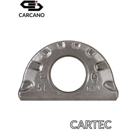
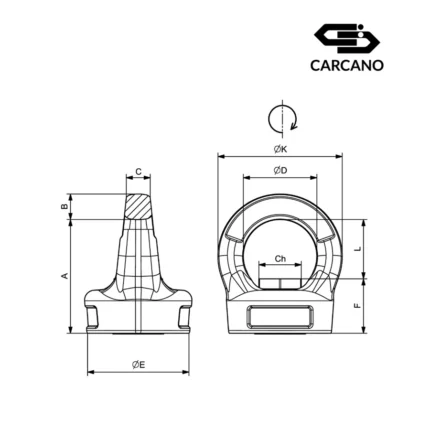
1.3 Markings
Each eyebolt has identification marking of the type, in compliance to the technical norms UNI EN 795, UNI EN 365 and UNI CEN/TS 16415 and the compliance marking Reg. EU 2016/425.
The elements which make up eyebolt marking as follows:
For production needs the positioning of the elements illustrated in marking may not correspond to the example above.
2. INSTRUCTIONS FOR USE
2.1 General provisions
The eyebolts described in this user manual are individual protection devices and as such are supplied to the user.
Must be put to use at the exact same time as the work begins and removed as soon as they no longer need to be installed as the work has been carried out.
These devices must be suitably mounted in the specific slots which are easy to detect that the user finds already set up on suitable structures (see point 3 “installation”).
Eyebolts must be used only for protection against falls from height or used for restraining if used with specific and suitable devices.
Must not be used for lifting equipment.
Use of eyebolts not as provided in this manual may be exposed to unforeseen risks that can result in serious injury to themselves and be permanent and in severe cases lead to death. When the anchorage device is used as part of a fall arrest system, each individual operator must have a means to limit the maximum dynamic strength exercised by the using during the fall arrest up to a maximum of 6 Kn.
It is absolutely necessary that staff using eyebolts and individual protection devices against falls from heights be informed about risks, and trained to use anti-fall devices end must be aware of the limits and precautions to take and the danger derived from incorrect use.
It is also necessary that the staff be in good physical condition and health in order to operate safety during normal operations and in emergencies. During use the user should not be under the influence of drugs or alcohol that can affect balance, attention and reflexes.
Eyebolts must not be used beyond the limitations of use or for other purposes other than the intended use (see point 2.8 “Limitations and precautions for use”).
Here follows a non-exhaustive and purely for information risk associated with use and cannot be eliminated of eyebolts and individual protection devices against falls from heights:
- main risks of falling as a result of falling from heights;
- risks arising subsequent to the fall by the oscillation of the body colliding with obstacles (pendulum effect): the stop of the motion of falling as a result of the stresses transmitted to the body harness, suspended from the inert body of the user is left hanging on the fall stop device and the time spent in this position;
- risk associated with individual protective equipment due to imperfect adaptability to the user; from obstruction to freedom of movement caused by the devices themselves;
- risk triggering the fall resulting from insufficient adhesion of footwear; from dizziness, glare from eyes, poor visibility, heat or sun stroke, or rapid drop in temperature;
- specific work risk which can be mechanical in nature (sharp edges, sharp tools, falling objects, etc.) thermal in nature (sparks, flames etc.,) chemical or electrical in nature.
- risks arising from atmospheric situations, wind, rain or ice on walking surfaces
2.2 Individual protection equipment
Eyebolts must be used exclusively in conjunction with fall prevention equipment for protection against falls from heights. You must also take into consideration the fact that also other individual protection equipment used fall within the scope of Reg. EU 2016/425 and are required to be marked CE and have all the necessary documentation and support.
It is strictly forbidden to use individual protection equipment against protection from falls from heights which are not in compliance to the essential safety end health requisites Annexed Reg. EU 2016/425.
It must be taken into consideration that a body harness is the only equipment which is suitable to be used for fall prevention protection.
When the free air draft is determined under the walking surface a suitable prevention fall device must be selected in order to make the fall stop distance minimum.
A harness with a retractable fall prevention device offers the use greater mobility exposing it to a greater pendulum effect which may need installation of fall deviation anchorage devices. A harness with an anti-fall cord with an integrated energy absorber (maximum length 2 m.) offers user lower mobility but reduces the pendulum effect in case of a fall.
We would like to draw your attention to the fact on the market there are several connection devices available (energy absorbers, cords etc.) that have different lengths, characteristics and performance. It is absolutely necessary that when choosing the individual protection equipment careful evaluation is made regarding all the foreseeable factors which can be of Influence. For example, the position of the eyebolts has to be kept in mind and the maximum height of free fall which is available before deciding if a retractable fall prevention device should be used or if an energy absorber should be used with an integrated cord. In general, all the devices which are in compliance to norms EN 355 and EN 360 can be used which have connectors (the ones which are used to connect to an anchorage point) In compliance to the norm EN 362 the spring catch type (allowed class B and M, allowed class A and T with some restrictions related to the body of the connector and to the measures, consider the verifications described below).
However always make sure that:
- lf the device is used by two people simultaneously the connectors do not overlap:
- The body of the connections pass easily through the eyebolt ring and the lever of the connectors close easily and completely;
- The closed and locked connectors can move freely inside the eyebolt ring.
lf these conditions are not executed, connection lo the anchorage point Is to be considered NOT compatible and MUST NOT be used for any reason whatsoever.
Compatibility of all the protection equipment used must be taken into careful consideration.
For effective end sale use of the eyebolts all the user manuals that are provided must be read and understood
2.3 Emergency Plan
For all the activities involving risk of falling from heights an adequate contingency plan must be put into place (called risk assessment in the manual or safety operation plan if applicable) which contains measures or actions that limit the maximum inert suspension time of operator unconsciousness who has fallen (possibly a few minutes).
The manufacturer declaims any liability arising from a faulty drafting of the document risk assessment and/or operational level of security (if applicable) and/or the specific emergency plan/
2.4 Assembly and Disassembly
Once a suitable point on the structure has been identified which has already been predisposed and deemed suitable to provide adequate protection for the type of work to be carried out, install a suitable eyebolt for the chosen anchorage point.
The holes on the structure provided to house the eyebolts are made clearly visible for the operators through adequate marking or appropriate colour schemes (see point 3 “installation”).
Warning – During assembly of the eyebolts the operator may be in an unsafe condition. AII the necessary precautions must be taken for safe installation, for example barriers, use of lifts, collective protection devices etc.
During all the phases of installation particular attention to the fact that the area below is clear of people things and animals.
The right Allen key for the clam must be removed after assembly: it must be kept with the persona! equipment of the operator.
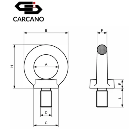
Mod. 900HT M16 – M20 / 902HT M16 – M20
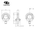
Screwing the treaded part of the bolt in the proper treaded hole, blind or tapped, using the right Allen key until the lower surface of the device sticks to the flat part of the structure.
Screw on the threaded part of the eyebolt in the suitable hole, blind or through hole using the socket head spanner provided with the eyebolt until the bottom part of the device touches the surface of the structure.
Tighten the screw manually with the socket head spanner without the use of extension cords that could be pre-loaded with excessive torque.
When it has been tightened make sure that the device rotates freely and correctly.
To disassemble proceed in the reverse way.
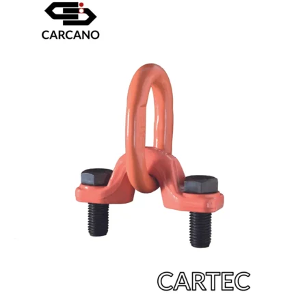
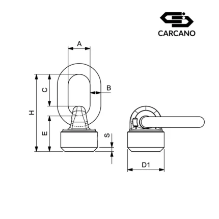
Mod. 901HT M16 – M20 / 903HT M16 – M20
Insert the threaded part of the eyebolt in the through hole; make the lower part of the device on the surface of the host structure: Insert the DIN 5340 washer and manually screw the counter net to its end (if the washer and the nut are provided directly by the producer use those included).
Insert washer DIN 6340 which is provided and manually screw on until it is flush with the nut which is also provided. Manually screw on the screw with the socket head spanner and to lock the nut use a fixed spanner without aid of extensions which could preload the screw with excessive torque. When locking has been executed make sure that the device rotates freely and correctly. To disassemble proceed in the reverse way.
Warning – The device must not in any way be used with holes that do not have an appropriate length which prevent correct fixing of the device
High counter nuts if not provided by the producer must be at least class 10 far devices code 901HT and at least class A4-80 for stainless steel devices code 903HT.
During assembly or disassembly extra care must be taken not to deform eyebolts and in particular the threaded part and do not subject all the components to excess stress, crashes and any other operation that can alter the safety features.
lf during assembly or disassembly you see deformed parts even if only slightly they must be replaced
2.5 Checks before use
Before using each time make sure that:
- The device and all its components including the screw have no signs of faults, wear, corrosion, deformation or accidental cuts;
- Markings are clearly visible;
- The diameter of the ring has not decreased more than 70% of the nominal diameter of the ring itself due to wear in one or several contact points;
- Anything else that might affect safety conditions of the eyebolts.
Warning – If the device has fallen or if doubts a rise in relation to suitability of using the device replace it with another device!
2.6 Use
The position of the device is fundamental for the safety of the fall stop and safeguard of the operator therefore:
- Make sure to use the anchorage point right above the user;
- Carefully assess the height of the fall, lengthening of the connecl1on device and the “pendulum” effect making sure there is enough free space to avoid accidental crashes with possible obstacles or the ground;
- Assess if in the event of a fall the capacity of the connection device (cord) due to rubbing, squeezing, crashes, blocks and cuts (e.g. cutting edges) or other is net affected;
Before gaining access to the work place, the user must put on (it is obligatory) a body harness and connect it to a connection device.
It is necessary for the fall prevention device to the eyebolts to always be positioned as near to the user as possible and aligned with respect to the potential direction of the fall in order to minimize the pendulum effect
In case of a fall it would be best if possible to abandon all the objects held in hand in order to avoid being hit when hitting the floor.
To guarantee maximum efficiency and safety of the eyebolts the user must inform the supervisor if there are any anomalies in the work area or on the eyebolts themselves in order to resolve the issues and improve efficiency.
2.7 Limits/ precautions of use
Eyebolts must only be used to protect users against falling from heights or far restraining purposes if used with suitable devices. If the eyebolts are used for any other situation other than the use described in this manual users can undergo serious risks which have not been taken into account and be seriously Injured, also causing permanent injury and at in worst case scenarios even cause death.
It is strictly forbidden to simultaneously connect many users at the same eyebolt.
It is absolutely forbidden to use the eyebolts as an application point to lift loads.
It is absolutely forbidden to disconnect from the eyebolt while still exposed to the risk of falling from heights.
Do not use the devices in acidic or highly corrosive environments due to chemical substances and or in explosive environments.
Do not use for purposes other than those specified.
Do not use the device for lifting equipment.
Do not use the device for recreational or sports activities.
Do not use the device for hook type DIN 5290.
Eyebolts do not turn when loaded.
Eyebolts must not be used at temperatures which are lower than -40°C and higher than 280°C
Do not replace the screws and all the original components.
Assess any risks that may rise from the use of combinations of items of equipment in which the safe operation of each item is influenced or interferes with the safe operation of another one.
lf changes or repairs and or subsequent treatments are carried out, the warranty terms are void and Stamperia Carcano shall be deemed exempt from any liability
3. INSTALLATION
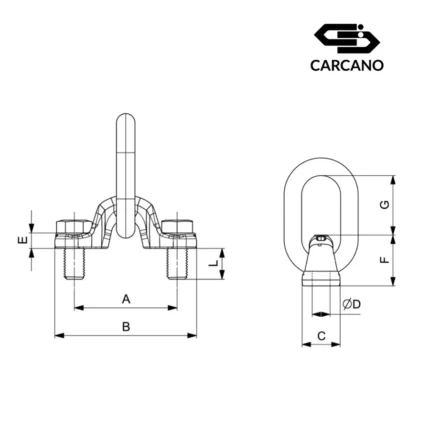
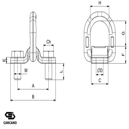
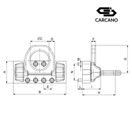
3.1 Characteristics of the models
3.2 General remarks
The information in this chapter are exclusively for the person in charge of the calculations to check the resistance of the structure and/or for the person who makes the holes on the structure.
3.3 General set ups for installation purposes
lf the eyebolts are kept in the warehouse before installation, special care must be taken – they must be kept in a dry place and protected from aggressive environments that could alter the safety characteristics.
During all the work phases special care must be taken so that there are no people, animals or things in the area beneath.
During work the operator can be in a non-protected condition, therefore, all the necessary precautions must be taken to carry out installation safely (e.g. barriers, use of elevators with baskets, collective protection devices, etc.)
The mechanical characteristics of the structure which houses the anchorage device must be steel and must guarantee a traction resistance exceeding 340 N/mm2 (e.g.: steel 8235JR [1.00371)
Both the blind or threaded hole e (mod. 900HT-902HT M1 6-M20) as well as the non-threaded tapped hole (mod. 901 HT-903HT M1 6-M20), must be perpendicular to the surface.
Mod. 900HT-902HT M16-M20
The depth of the threaded hole must be a minimum 1.5 times the diameter of the screw
Mod. 901 HT-903HT M16-M20
The tapping hole on the main structure must be perpendicular to the support surface and must have a maximum diameter of 2 mm with respect to the nominal diameter of the screw used.
Fixing components made of other material must be authorized and approved by the manufacturer.
Taking into account that it is forbidden to use the device with parts of the surface cantilevered make sure that the surface of the mother screw is suitable in terms of planarity and dimension in order to ensure the support of the entire surface of the device and that it can adhere properly.
3.4 Configuration and positioning
Anchorage points must be calculated and verified in order to be structurally capable of withstanding stress generated by a free fall of the operator in the worst conditions.
These paints must be clearly visible and identifiable by the operator who has to assemble the eyebolts, and therefore for this purpose must be identified by a yellow outline.
The person who prepares the structure must also highlight by marking at every point which must be clear, legible and indelible:
- The type of eyebolt can house (e.g. EN795-900HT-902HT M16 o EN795-907 HT-903HT M16)
- Suitable fall prevention device (e.g. EN355 or EN360)
- Air draft available
The anchorage devices must be positioned in fall risk points consistent with the need to move as required in order to achieve the minimum height at free fall.
The lapping hole on the main structure must be perpendicular to the support surface and must have a maximum diameter of 2 mm with respect to the nominal diameter of the screw used.
Access to any structure or cover must always be secure. The eyebolt system must be designed so that the user can access it safely and that the fall prevention card or retractable fall protection device, can be connected to the same BEFORE the user is in a dangerous position of falling from heights. On the contrary there must be an alternative safe access for example using another fall prevention device.
It is essential for safety that the anchorage point is always positioned in such a way so as to minimize both the risk of falling and the potential fall distance. It is necessary to conduct a thorough analysis of the area where you plan to install the eyebolts taking into account these two factors.
When possible the eyebolts have to be installed higher than the connection point of the user’s fall prevention system.
To define the position of the eyebolts it is advisable to check the air draft taking into consideration the following:
- Length of the connection between the harness and the anchorage point;
- Capacity of anti-fall prevention device (extension during fall stop);
- Position of walking surface with respect to the anchorage point;
- Height of the user;
- Possible side movement of the anchorage point with respect to the fall direction (pendulum effect);
- An additional meter for safety measures is needed due to unexpected factors (elasticity of the materials, non-rigid behaviour of user’s body etc.).
Finally, it is essential to foresee cases in which the work area may be considerably moved to a different position with respect to the anchorage point. In these cases, during a fall stop, a pendulum effect may occur. The user while falling is dragged along the wall towards the vertical side along the anchorage point.
lf it is possible that during the pendulum effect the user runs in to an obstacle it is necessary to provide a different configuration to the anchorage system (for example a routing anchorage).
3.5 Limits for installation and special warnings
Installation of eyebolts is STRICTLY PROHIBITED in facilities that at the discretion of the installer and after consulting a qualified engineer show a state of inadequate preservation and or consistency.
The instructions in this section are the generalization of the different types of installation that the manufacture is reasonably able to predict.
However, given the wide variety of cases and possible geometry (size, thickness etc.) you must always act according to common sense.
lf in doubt do not interpret. The manufacturer is always available to solve any problems or can provide useful addresses to resolve any problems. Never act if you are not sure of what you are doing.
3.6 Inspections at regular intervals
Inspections at regular intervals are carried out to verify that the eyebolts safety features remain unchanged over time and therefore it is necessary to inspect them at regular intervals (usually at least once a year).
It is advisable to make sure that the installation points that have already been set up on the structures designed to house the eyebolts undergo inspections at regular intervals by the people in charge.
The safety or users depends on their continued efficiency and durability.
Scheduling of inspections at regular intervals should take into account the following factors such as, frequency of use and environmental conditions in which the eyebolts operate that may make it necessary to carry out inspections more frequently. The results of the regular inspections must be recorded on a specific inspection (see point 5 “recordings”).
Regular inspections have to be carried out only by the manufacturer or a competent person authorized by the manufacturer.
During regular inspections legibility of the markings must be checked for identification of the eyebolts.
If during installation the marking of the device is not accessible, it is advisable to have an additional marking close to the anchorage device.
4. MAINTENANCE
The information in this manual are addressed for the user and only for standard maintenance.
Given the characteristics of the eyebolts no routine maintenance operations are foreseen. However, they should always be kept in good condition by regularly removing dirt/
For safety reasons repairs nor modifications are allowed even if not considered significant. Any repairs can be carried out by the manufacturer or by a competent person authorized by the manufacturer.
No special maintenance is foreseen to be carried out by the user (for example following a fall or other special events), if necessary the manufacturer of by a competent person authorized by the manufacturer.
4.1 Storage and Disposal
Eyebolts have to be stored in a dry, non-corrosive place far from heat and direct sunlight.
AII components have to disposed of and taken to specific collection areas for metal scrap in compliance to the laws in force.
5. RECORDINGS
Revolving prevention fall devices mod. 900HT, 901HT, 902HT and 903HT are subject to scheduled and regular inspections and registered in a specific recording form in compliance to the laws in force.
The results of the inspections and any interventions that have been carried out must be quoted on the forms and the expiry date and subsequent control.


Reviews
There are no reviews yet.